
Mastering
In this tutorial, we will deploy and run the SD-Core 5G core network following Control Plane and User Plane Separation (CUPS). The User Plane will be deployed in DPDK mode. The radio and cell phone simulator will also be deployed on an isolated cluster. This tutorial uses LXD with Terraform to deploy the required infrastructure.
1. Prepare the Host machine
A machine running Ubuntu 22.04 with the following resources:
At least one NIC with internet access
8 cores
32 GB RAM
150 GiB disk
Networks
The following IP networks will be used to connect and isolate the network functions:
Name |
Subnet |
Gateway IP |
|---|---|---|
|
10.201.0.0/24 |
10.201.0.1 |
|
10.202.0.0/24 |
10.202.0.1 |
|
10.203.0.0/24 |
10.203.0.1 |
|
10.204.0.0/24 |
10.204.0.1 |
Install and Configure LXD
Install LXD:
sudo snap install lxd
Initialize LXD:
sudo usermod -aG lxd "$USER"
newgrp lxd
lxd init --auto
Install Terraform
Install Terraform:
sudo snap install terraform --classic
2. Create Virtual Machines
To complete this tutorial, you will need four virtual machines with access to the networks as follows:
Machine |
CPUs |
RAM |
Disk |
Networks |
|---|---|---|---|---|
Control Plane Kubernetes Cluster |
4 |
8g |
40g |
|
User Plane Kubernetes Cluster |
4 |
12g |
20g |
|
Juju Controller + Kubernetes Cluster |
4 |
6g |
40g |
|
gNB Simulator Kubernetes Cluster |
2 |
3g |
20g |
|
The complete infrastructure can be created with Terraform using the following commands:
git clone https://github.com/canonical/charmed-aether-sd-core.git
cd charmed-aether-sd-core/terraform
terraform init
terraform apply -auto-approve
Note
Creating the complete infrastructure for the network will take approximately 20 minutes.
Terraform will output two MAC addresses - the access-mac-address and the core-mac-address. Note them for later.
Example Terraform output:
Apply complete! Resources: 18 added, 0 changed, 0 destroyed.

Outputs:

access-mac-address = {
  "out" = <<-EOT
  00:16:3e:2c:e4:8f

  EOT
}
core-mac-address = {
  "out" = <<-EOT
  00:16:3e:6c:60:de

  EOT
}
Checkpoint 1: Are the VM’s ready ?
You should be able to see all the VMs in a Running state with their default IP addresses by executing the following command:
lxc list
The output should be similar to the following:
+-----------------+---------+-----------------------+------+-----------------+-----------+
|      NAME       |  STATE  |         IPV4          | IPV6 |      TYPE       | SNAPSHOTS |
+-----------------+---------+-----------------------+------+-----------------+-----------+
| control-plane   | RUNNING | 10.201.0.101 (enp5s0) |      | VIRTUAL-MACHINE | 0         |
+-----------------+---------+-----------------------+------+-----------------+-----------+
| gnbsim          | RUNNING | 10.204.0.100 (enp6s0) |      | VIRTUAL-MACHINE | 0         |
|                 |         | 10.201.0.103 (enp5s0) |      |                 |           |
+-----------------+---------+-----------------------+------+-----------------+-----------+
| juju-controller | RUNNING | 10.201.0.104 (enp5s0) |      | VIRTUAL-MACHINE | 0         |
+-----------------+---------+-----------------------+------+-----------------+-----------+
| user-plane      | RUNNING | 10.203.0.100 (enp6s0) |      | VIRTUAL-MACHINE | 0         |
|                 |         | 10.202.0.100 (enp7s0) |      |                 |           |
|                 |         | 10.201.0.102 (enp5s0) |      |                 |           |
+-----------------+---------+-----------------------+------+-----------------+-----------+
3. Deploy SD-Core Control Plane
The following steps build on the Juju controller which was bootstrapped and knows how to manage the SD-Core Control Plane Kubernetes cluster.
First, we will create a new Terraform module which we will use to deploy SD-Core Control Plane. After the successful deployment, we will configure the Access and Mobility Management Function (AMF) IP address for sharing with the radios and the Traefik external hostname for exposing the SD-Core Network Management System (NMS). This host name must be resolvable by the gNB and the IP address must be reachable and resolve to the AMF unit. In the bootstrap step, we set the Control Plane MetalLB IP range, and that is what we use in the configuration. Lastly, the module will expose the Software as a Service offer for the AMF.
Log in to the juju-controller VM:
lxc exec juju-controller -- su --login ubuntu
Create new folder called terraform:
mkdir terraform
Inside newly created terraform folder create a versions.tf file:
cd terraform
cat << EOF > versions.tf
terraform {
  required_providers {
    juju = {
      source  = "juju/juju"
      version = ">= 0.12.0"
    }
  }
}
EOF
Create Terraform module:
cat << EOF > main.tf
data "juju_model" "control-plane" {
  name = "control-plane"
}

module "sdcore-control-plane" {
  source = "git::https://github.com/canonical/terraform-juju-sdcore//modules/sdcore-control-plane-k8s"

  model = data.juju_model.control-plane.name

  amf_config = {
    external-amf-hostname = "amf.mgmt.local"
  }
  traefik_config = {
    routing_mode = "subdomain"
  }
}

EOF
Initialize Juju Terraform provider:
terraform init
Deploy SD-Core Control Plane:
terraform apply -auto-approve
Monitor the status of the deployment:
juju switch control-plane
juju status --watch 1s --relations
The deployment is ready when all the charms are in the Active/Idle state.
It is normal for grafana-agent to remain in waiting state.
Once the deployment is ready, we will proceed to the configuration part.
Get the IP addresses of the AMF and Traefik LoadBalancer services:
Log in to the control-plane VM:
ssh control-plane
Get LoadBalancer services:
sudo k8s kubectl get services -A | grep LoadBalancer
This will show output similar to the following:
control-plane    amf-external  LoadBalancer  10.152.183.179  10.201.0.52   38412:30408/SCTP
control-plane    traefik-lb    LoadBalancer  10.152.183.28   10.201.0.53   80:32349/TCP,443:31925/TCP
Note both IPs - in this case 10.201.0.52 for the AMF and 10.201.0.53 for Traefik.
We will need them shortly.
Note
If the IP for the AMF is not 10.201.0.52, you will need to update the DNS entry to match the actual external IP for the AMF. In the host, edit the main.tf file. Find the following line and set it to the correct IP address, like so:
host-record=amf.mgmt.local,10.201.0.53
Then, run the following command on the host:
terraform apply -auto-approve
Log out of the control-plane VM.
Configure AMF external IP, using the address obtained in the previous step.
To do that, edit amf_config in the main.tf file in the terraform directory.
Updated amf_config should look like similar to the below:
(...)
module "sdcore-control-plane" {
  (...)
  amf_config = {
    external-amf-ip       = "10.201.0.52"
    external-amf-hostname = "amf.mgmt.local"
  }
  (...)
}
(...)
Configure Traefik’s external hostname, using the address obtained in the previous step.
To do that, edit traefik_config in the main.tf file.
Updated traefik_config should look like similar to the below:
(...)
module "sdcore-control-plane" {
  (...)
  traefik_config = {
    routing_mode      = "subdomain"
    external_hostname = "10.201.0.53.nip.io"
  }
  (...)
}
(...)
Apply the changes:
terraform apply -auto-approve
4. Deploy User Plane Function (UPF) in DPDK mode
Deploy sdcore-user-plane-k8s Terraform Module.
In the directory named terraform, update the main.tf file.
Please replace the access-interface-mac-address and core-interface-mac-address with the MAC addresses noted in 2. Create Virtual Machines.
cat << EOF >> main.tf
data "juju_model" "user-plane" {
  name = "user-plane"
}

module "sdcore-user-plane" {
  source = "git::https://github.com/canonical/terraform-juju-sdcore//modules/sdcore-user-plane-k8s"

  model = data.juju_model.user-plane.name

  upf_config = {
    cni-type                     = "vfioveth"
    upf-mode                     = "dpdk"
    access-gateway-ip            = "10.202.0.1"
    access-ip                    = "10.202.0.10/24"
    core-gateway-ip              = "10.203.0.1"
    core-ip                      = "10.203.0.10/24"
    external-upf-hostname        = "upf.mgmt.local"
    access-interface-mac-address = "c2:c8:c7:e9:cc:18" # In this example, its the MAC address of access interface.
    core-interface-mac-address   = "e2:01:8e:95:cb:4d" # In this example, its the MAC address of core interface
    enable-hw-checksum           = "false"
    gnb-subnet                   = "10.204.0.0/24"
  }
}

resource "juju_integration" "nms-upf" {
  model = data.juju_model.control-plane.name

  application {
    name     = module.sdcore-control-plane.nms_app_name
    endpoint = module.sdcore-control-plane.fiveg_n4_endpoint
  }

  application {
    offer_url = module.sdcore-user-plane.upf_fiveg_n4_offer_url
  }
}

EOF
Update the Juju Terraform provider:
terraform init
Deploy SD-Core User Plane:
terraform apply -auto-approve
Monitor the status of the deployment:
juju switch user-plane
juju status --watch 1s --relations
The deployment is ready when the UPF application is in the Active/Idle state.
It is normal for grafana-agent to remain in waiting state.
Checkpoint 2: Validate that the UPF is running in DPDK mode
Verify that DPDK BESSD is configured in DPDK mode by using the Juju debug log:
juju debug-log --replay | grep -i dpdk
You should see the following output:
unit-upf-0: 16:18:59 INFO unit.upf/0.juju-log Container bessd configured for DPDK
5. Deploy the gNB Simulator
The following steps build on the Juju controller which was bootstrapped and knows how to manage the gNB Simulator Kubernetes cluster.
First, we will add gNB Simulator to the Terraform module used in the previous steps. We will provide necessary configuration (please see the list of the config options with the description in the table below) for the application and integrate the simulator with the relevant 5G Core Network Functions (AMF, NMS and UPF).
Config Option |
Descriptions |
|---|---|
gnb-interface |
The name of the MACVLAN interface to use on the host |
gnb-ip-address |
The IP address to use on the gnb interface |
icmp-packet-destination |
The target IP address to ping. If there is no egress to the internet on your core network, any IP that is reachable from the UPF should work. |
upf-gateway |
The IP address of the gateway between the RAN and Access networks |
upf-subnet |
Subnet where the UPFs are located (also called Access network) |
Update the main.tf file:
cat << EOF >> main.tf
data "juju_model" "gnbsim" {
  name = "gnbsim"
}

module "gnbsim" {
  source = "git::https://github.com/canonical/sdcore-gnbsim-k8s-operator//terraform"

  model = data.juju_model.gnbsim.name

  config = {
    gnb-interface           = "ran"
    gnb-ip-address          = "10.204.0.10/24"
    icmp-packet-destination = "8.8.8.8"
    upf-gateway             = "10.204.0.1"
    upf-subnet              = "10.202.0.0/24"
  }
}

resource "juju_integration" "gnbsim-amf" {
  model = data.juju_model.gnbsim.name

  application {
    name     = module.gnbsim.app_name
    endpoint = module.gnbsim.requires.fiveg_n2
  }

  application {
    offer_url = module.sdcore-control-plane.amf_fiveg_n2_offer_url
  }
}

resource "juju_integration" "gnbsim-nms" {
  model = data.juju_model.gnbsim.name

  application {
    name     = module.gnbsim.app_name
    endpoint = module.gnbsim.requires.fiveg_core_gnb
  }

  application {
    offer_url = module.sdcore-control-plane.nms_fiveg_core_gnb_offer_url
  }
}

EOF
Update Juju Terraform provider:
terraform init
Deploy the gNB simulator:
terraform apply -auto-approve
Monitor the status of the deployment:
juju switch gnbsim
juju status --watch 1s --relations
The deployment is ready when the gnbsim application is in the Waiting/Idle state and the message is Waiting for TAC and PLMNs configuration.
6. Configure SD-Core
The following steps show how to configure the SD-Core 5G core network. In this step we will create a network slice, a device group and a subscriber.
Retrieve the NMS credentials (username and password):
juju switch control-plane
juju show-secret NMS_LOGIN --reveal
The output looks like this:
cvn3usfmp25c7bgqqr60:
  revision: 2
  checksum: f2933262ee923c949cc0bd12b0456184bb85e5bf41075028893eea447ab40b68
  owner: nms
  label: NMS_LOGIN
  created: 2025-04-03T07:57:40Z
  updated: 2025-04-03T08:02:15Z
  content:
    password: pkxp9DYCcZG
    token: eyJhbGciOiJIUzI1NiIsInR5cCI6IkpXVCJ9.eyJleHAiOjE3NDM2NzA5MzMsInVzZXJuYW1lIjoiY2hhcm0tYWRtaW4tVlNMTSIsInJvbGUiOjF9.Qwp0PIn9L07nTz0XooPvMb8v8-egYJT85MXjoOY9nYQ
    username: charm-admin-VSLM
Retrieve the NMS address:
juju run traefik/0 show-proxied-endpoints
The output should be https://control-plane-nms.10.201.0.53.nip.io/.
Navigate to this address in your browser and use the username and password to login.
Assign Tracking Area Code (TAC) to the gNodeB
In the Network Management System (NMS) navigate to the Inventory tab. Click the Edit button next to the integrated gNB name and set TAC to 1:
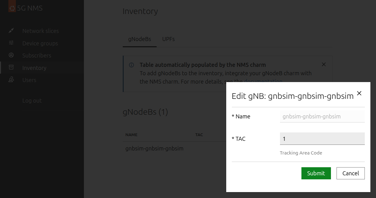
Confirm new TAC value by clicking the Submit button.
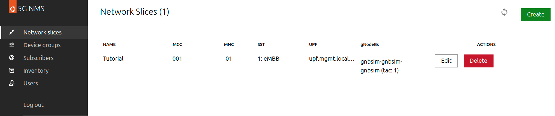
Create a Network Slice
Navigate to the Network slices tab and create a network slice with the following attributes:
Name:
TutorialMCC:
001MNC:
01UPF:
upf.mgmt.local:8805gNodeB:
gnbsim-gnbsim-gnbsim (tac:1)
You should see the following network slice created.
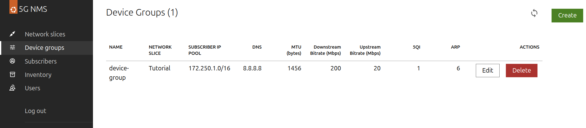
Create a Device Group
Navigate to the Device groups tab and create a device group with the following attributes:
Name:
device-groupNetwork Slice:
TutorialSubscriber IP pool:
172.250.1.0/16DNS:
8.8.8.8MTU (bytes):
1456Maximum bitrate (Mbps):
Downstream:
200Upstream:
20
QoS:
5QI:
1: GBR - Conversational VoiceARP:
6
You should see the following device group created:
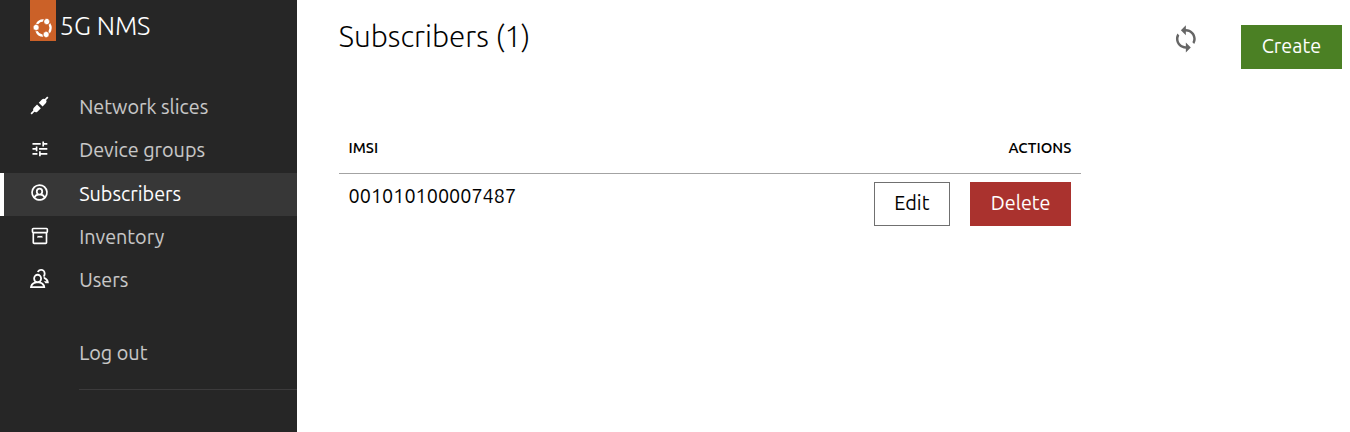
Create a Subscriber
Navigate to Subscribers tab and click the Create button. Fill in the following:
Network Slice:
TutorialDevice Group:
device-group
Click the two Generate buttons to automatically fill in the values in the form. Note the IMSI, OPC, and Key; we are going to use them shortly.
After clicking the Submit button you should see the subscriber created:
7. Integrate SD-Core with the Canonical Observability Stack (COS)
The following steps show how to integrate the SD-Core 5G core network with the Canonical Observability Stack (COS).
First, we will add COS to the Terraform module used in the previous steps. Next, we will expose the Software as a Service offers for the COS and create integrations with SD-Core 5G core network components.
Deploy COS Lite
Add cos-lite Terraform module to the main.tf file used in the previous steps:
cat << EOF >> main.tf
module "cos-lite" {
  source = "git::https://github.com/canonical/terraform-juju-sdcore//modules/external/cos-lite"

  model_name               = "cos-lite"
  deploy_cos_configuration = true
  cos_configuration_config = {
    git_repo                 = "https://github.com/canonical/sdcore-cos-configuration"
    git_branch               = "main"
    grafana_dashboards_path  = "grafana_dashboards/sdcore/"
  }
}

EOF
Update Juju Terraform provider:
terraform init
Deploy COS:
terraform apply -auto-approve
Monitor the status of the deployment:
juju switch cos-lite
juju status --watch 1s --relations
The deployment is ready when all the charms are in the Active/Idle state.
Integrate SD-Core with COS Lite
Once the COS deployment is ready, add integrations between SD-Core and COS applications to the main.tf file:
cat << EOF >> main.tf
resource "juju_integration" "control-plane-prometheus" {
  model = data.juju_model.control-plane.name

  application {
    name     = module.sdcore-control-plane.grafana_agent_app_name
    endpoint = module.sdcore-control-plane.send_remote_write_endpoint
  }

  application {
    offer_url = module.cos-lite.prometheus_remote_write_offer_url
  }
}

resource "juju_integration" "control-plane-loki" {
  model = data.juju_model.control-plane.name

  application {
    name     = module.sdcore-control-plane.grafana_agent_app_name
    endpoint = module.sdcore-control-plane.logging_consumer_endpoint
  }

  application {
    offer_url = module.cos-lite.loki_logging_offer_url
  }
}

resource "juju_integration" "user-plane-prometheus" {
  model = data.juju_model.user-plane.name

  application {
    name     = module.sdcore-user-plane.grafana_agent_app_name
    endpoint = module.sdcore-user-plane.send_remote_write_endpoint
  }

  application {
    offer_url = module.cos-lite.prometheus_remote_write_offer_url
  }
}

resource "juju_integration" "user-plane-loki" {
  model = data.juju_model.user-plane.name

  application {
    name     = module.sdcore-user-plane.grafana_agent_app_name
    endpoint = module.sdcore-user-plane.logging_consumer_endpoint
  }

  application {
    offer_url = module.cos-lite.loki_logging_offer_url
  }
}

EOF
Apply the changes:
terraform apply -auto-approve
Checkpoint 3: Validate that the Grafana dashboard available
From the juju-controller VM, retrieve the Grafana URL and admin password:
juju switch cos-lite
juju run grafana/leader get-admin-password
This produces output similar to the following:
Running operation 1 with 1 task
  - task 2 on unit-grafana-0

Waiting for task 2...
admin-password: c72uEq8FyGRo
url: http://10.201.0.51/cos-lite-grafana
Note
Grafana can be accessed using both http (as returned by the command above) or https.
In your browser, navigate to the URL from the output (https://10.201.0.51/cos-lite-grafana).
Login using the “admin” username and the admin password provided in the last command.
Click on “Dashboards” -> “Browse” and select “5G Network Overview”.
This dashboard presents an overview of your 5G Network status. Keep this page open, we will revisit it shortly.
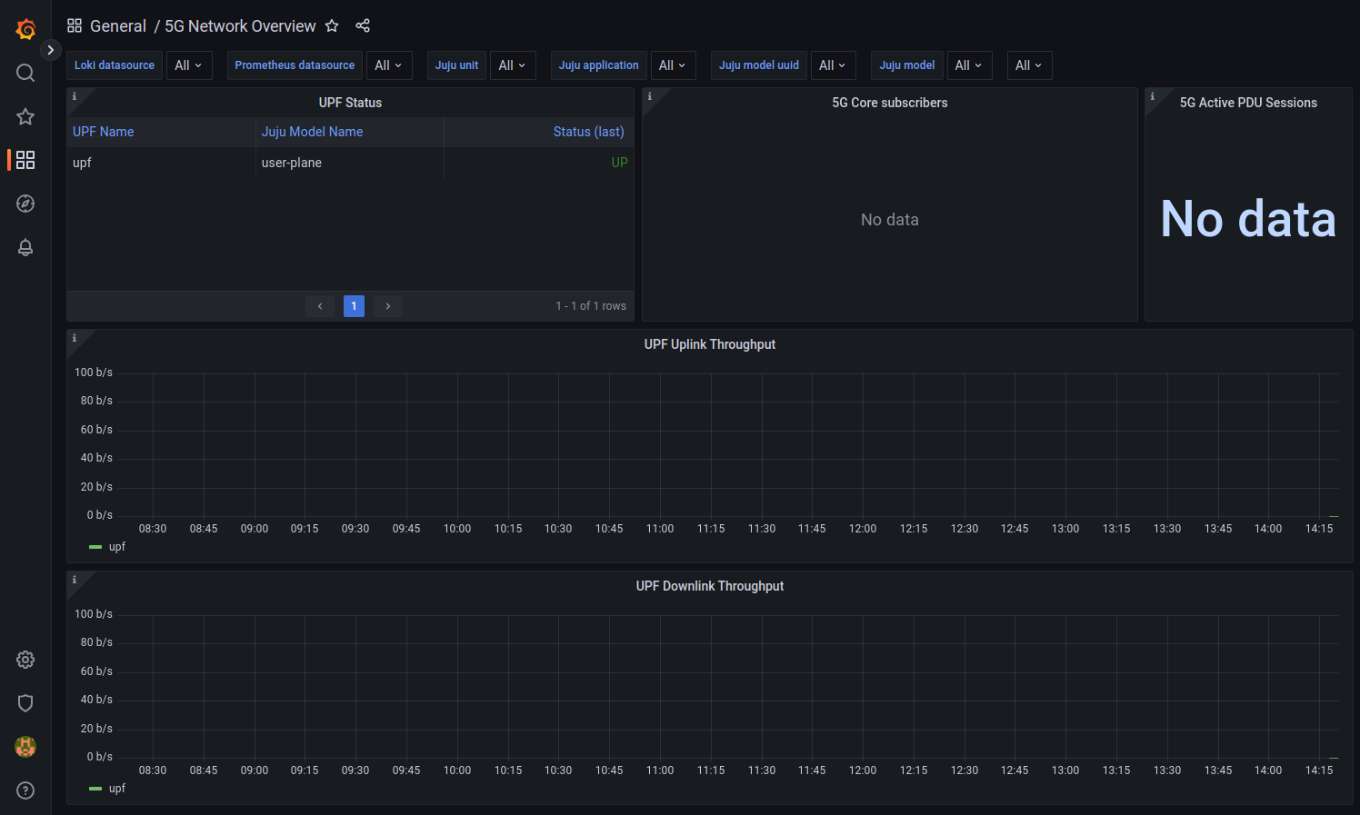
Note
It may take up to 5 minutes for the relevant metrics to be available in Prometheus.
Set up the subscriber information using Terraform module
From the juju-controller VM, add a config block to the gnbsim module in your main.tf file to configure gnbsim with the subscriber information.
Replace the placeholders with the values noted in step 6.
:caption: main.tf
module "gnbsim" {
  # ...
  config = {
    (...)
    imsi      = "<IMSI>"
    usim-opc  = "<OPC>"
    usim-key  = "<Key>"
  }
  # ...
Apply the updated configuration:
terraform apply -auto-approve
8. Run the 5G simulation
Switch to the gnbsim model:
juju switch gnbsim
Wait for the gnbsim status to be Active/Idle.
juju status --watch 1s --relations
Start the simulation.
juju run gnbsim/leader start-simulation
The simulation executed successfully if you see success: "true" as one of the output messages:
Running operation 1 with 1 task
  - task 2 on unit-gnbsim-0

Waiting for task 2...
info: 5/5 profiles passed
success: "true"
Checkpoint 4: Check the simulation logs to see the communication between elements and the data exchange
gNB Simulation Logs
Let’s take a look at the juju debug-log now by running the following command:
juju debug-log --no-tail
This will emit the full log of the simulation starting with the following message:
unit-gnbsim-0: 16:43:50 INFO unit.gnbsim/0.juju-log gnbsim simulation output:
As there is a lot of output, we can better understand if we filter by specific elements.
For example, let’s take a look at the control plane transport of the log.
To do that, we search for ControlPlaneTransport in the Juju debug-log.
This shows the simulator locating the AMF and exchanging data with it.
$ juju debug-log | grep ControlPlaneTransport
2023-11-30T16:43:40Z [TRAC][GNBSIM][GNodeB][ControlPlaneTransport] Connecting to AMF
2023-11-30T16:43:40Z [INFO][GNBSIM][GNodeB][ControlPlaneTransport] Connected to AMF, AMF IP: 10.201.0.52 AMF Port: 38412
...
We can do the same for the user plane transport to see it starts on the RAN network with IP address 10.204.0.10 as we requested, and it is communicating with our UPF at 10.202.0.10 as expected.
To follow the UE itself, we can filter by the IMSI (use the value from step 6).
juju debug-log | grep imsi-<IMSI>
Control Plane Logs
You may view the control plane logs by logging into the control plane cluster and using Kubernetes commands as follows:
sudo k8s kubectl logs -n control-plane -c amf amf-0 --tail 70
sudo k8s kubectl logs -n control-plane -c ausf ausf-0 --tail 70
sudo k8s kubectl logs -n control-plane -c nrf nrf-0 --tail 70
sudo k8s kubectl logs -n control-plane -c nssf nssf-0 --tail 70
sudo k8s kubectl logs -n control-plane -c pcf pcf-0 --tail 70
sudo k8s kubectl logs -n control-plane -c smf smf-0 --tail 70
sudo k8s kubectl logs -n control-plane -c udm udm-0 --tail 70
sudo k8s kubectl logs -n control-plane -c udr udr-0 --tail 70
Checkpoint 5: View the metrics
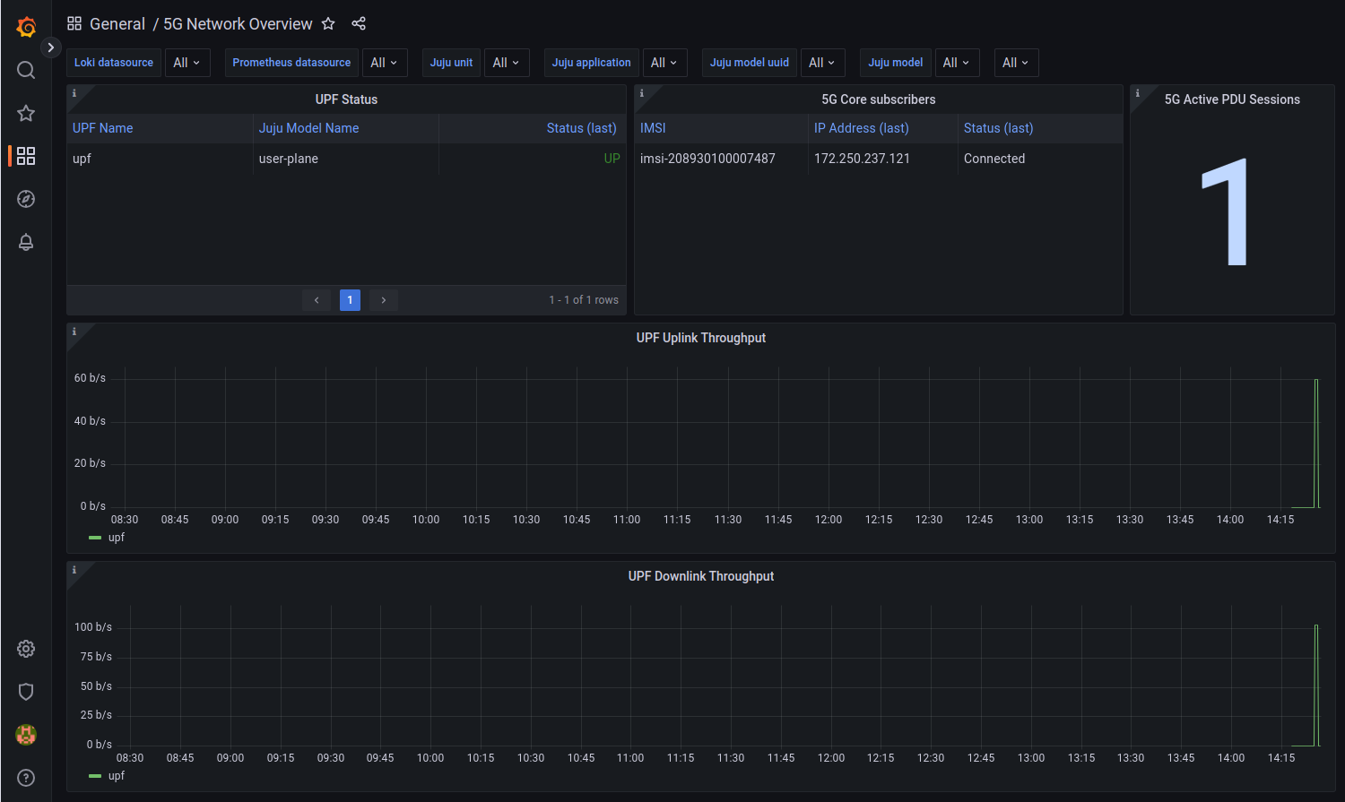
Grafana Metrics
You can also revisit the Grafana dashboard to view the metrics for the test run. You can see the IMSI is connected and has received an IP address. There is now one active PDU session, and the ping test throughput can be seen in the graphs.
9. Review
We have deployed 4 Kubernetes clusters, bootstrapped a Juju controller to manage them all, and deployed portions of the Charmed Aether SD-Core software according to CUPS principles. You now have 5 Juju models as follows:
control-planewhere all the control functions are deployedcontrollerwhere Juju manages state of the modelscos-litewhere the Canonical Observability Stack is deployedgnbsimwhere the gNB simulator is deployeduser-planewhere all the user plane function is deployed
You have learned how to:
view the logs for the various functions
manage the integrations between deployed functions
run a simulation testing data flow through the 5G core
view the metrics produced by the 5G core
Note
For your convenience, a complete Terraform module covering the deployments and integrations from this tutorial, is available in this Git repository.
All necessary files are in the examples/terraform/mastering directory.
10. Cleaning up
On the host machine, destroy the Terraform deployment to get rid of the whole infrastructure:
terraform destroy -auto-approve
Note
Terraform does not remove anything from the working directory.
If needed, please clean up the terraform directory manually by removing everything except for the main.tf and versions.tf files.